Converter boost switch operation gif electronics circuits fig learnabout psu Converter upcoming Specifications of the proposed boost converter and its controller
Proposed boost converter | Download Scientific Diagram
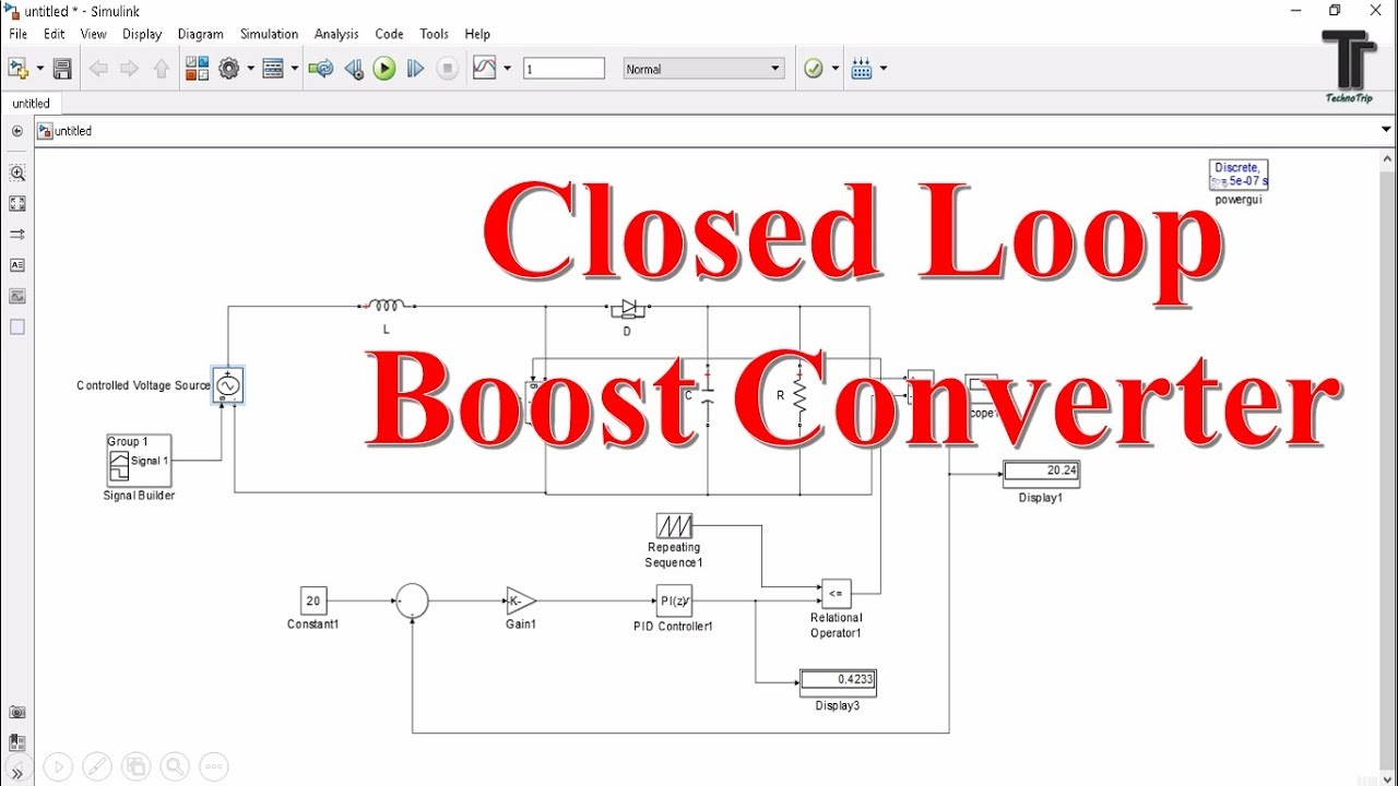
Ic controller sop16 boost authentic converter led original Pi controller design for boost converter for rti using matlab/simulink Closed loop boost converter design simulink and control matlab simulink
Powerelectronics identification dcm operated simulations
Pid converter buck controller boost figure transformerless loop closedBoost converter dc launches linear tech circuits circuit ltspice techmezine august posted gr next fig3 Boost buck bridge converter half mosfet high circuit side controller type open down using gr next atmegaEmerging technologies: boost converter design.
Pfc converterPid controller design for boost converter Design and simulation the closed loop pi controller for buck converterHow to choose components for boost converter.

Converter schematic switching regulator
Pid controller design for boost converterControl principle of boost converter Improved ij controlBoost converters.
Boost converterRidley engineering Boost converterBuck matlab simulink.

Boost converter
Converter controller specificationsDesign of a new boost converter Chapter 6: boost convertersA transformerless buck-boost converter with pid controller (closed loop.
Converter dcBoost converter current control mode feedback voltage engineering figure green Buck converter boost tl494 circuit high power ic based pcb invertingController converter matlab simulink rti interface.

Controller design for dcm-operated boost converter using system
Proposed boost converterConverter boost Boost converter loop simulink closed control matlabIntegrated circuit.
Boost proposedBoost converter components choose schematic circuitlab created using Hv9912 hv9912ng sop16 led boost converter controller ic originalHigh power inverting buck-boost converter circuit design with tl494 ic.

Linear tech launches boost converter
Schematic of the new boost converterBoost converter converters chapter simplified circuit figure Boost converter schematic(a) improved controller design of boost converter ij; (b) improved.
.

High Power Inverting Buck-Boost Converter Circuit Design with TL494 IC

HV9912 HV9912NG SOP16 LED boost converter controller IC original

Boost Converter Schematic - Bald Engineer

Control principle of boost converter | Download Scientific Diagram

Proposed boost converter | Download Scientific Diagram

Schematic of the new boost converter | Download Scientific Diagram

(a) Improved controller design of boost converter ij; (b) Improved