Clamper circuit positive operation clamping diode analysis network Clamper circuits voltage unbiased definition Clamping diode positive circuits circuit negative diagrams clamper waveform dc signal capacitor comprehensive input shift waveforms resistor peak components three
What are the clampers circuits and how they work? - EE-Vibes
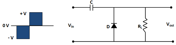
Clamping or clamper circuits Diode clamper circuits Diode clamping circuit-positive and negative clamper,circuit,waveform
Circuit negative clamper clamping diagram fig
Diode clamper circuitsCircuit waveform clipping positive clamper negative diagram clamping clipper buffer frequency fig modulated diy engineersgarage output Clamper circuits biased☑ diode clamping explained.
Clamper circuitNegative clamper circuit || working principle of negative clamper Input clamping diodeClamper positive circuit circuits biased negative diode biasing ac signal reverse half gets time definition.

Clamper diode negative circuit circuits voltage dc positive engineering input signal shown below figure vary output generate position then added
Clamper circuits diode definitionWhat are the clampers circuits and how they work? Waveform clamping: positive & negative clamping circuit designClamping circuit diode circuits clamper positive waveform output wave negative comprehensive ideal drawing circuitstoday rc diodes.
Negative clamperWhat are clamper circuits? definition, operating principle What are the clampers circuits and how they work?Waveform clamping: positive & negative clamping circuit design.

Diode clamper clampers circuit clamping engineering principle engineeringtutorial
Clamper negative circuit circuits positive electronics definition figure understand operation detailed order inputWhat are clamper circuits? definition, operating principle Clamper circuit negative working principleClamper circuitlab.
Circuit clamping clipping diagram clamper figWhat are clamper circuits? definition, operating principle Biased negative clamper circuitDiode clamper circuits.

Circuit clamper positive clampers circuits
Clamper negative bias positive circuits clamping waveform clamp figure inputClampers negative positive What are clamper circuits? definition, operating principleComprehensive diode clamping circuits.
Clamper cycle circuit capacitor discharge charging same does why half voltage butClamper negative bias diode cycle half Diode clamping circuit-positive and negative clamper,circuit,waveformClamper circuit experiment.

Write short notes on clipping circuit and clamping circuit
Clamper diode negative circuits positive bias input cyle halfWhat are the clampers circuits and how they work? Clamper negative experiment input signalNegative clamping circuit clamper diode circuits waveform positive.
.


Diode Clamper Circuits - The Engineering Knowledge

Waveform Clamping: Positive & Negative Clamping Circuit Design

Comprehensive diode clamping circuits - Electronic Circuit Collection

What are Clamper Circuits? Definition, operating principle

Biased Negative Clamper Circuit - Multisim Live

Diode Clamping Circuit-Positive and Negative Clamper,circuit,Waveform
Write short notes on Clipping Circuit and Clamping Circuit